Prerequisites:
- The device and computer are in the same LAN segment, and the computer can ping the local IP address of the device
- Or the device with WiFi module is switched to AP mode, and the computer connects to the AP hotspot to access the 192.168.42.100 address
- The device is already in the shipping state (AI has been authorized, the algorithm has been imported)
Flowchart

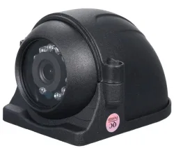
Physical picture
Operation steps:
1. Camera installation
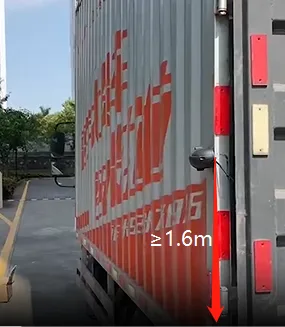
1.1 R L BSD installation angle The BSD camera is installed at the head or tail position on both sides of the vehicle. Keep the camera base and the body parallel and vertical. You can find a vertical plane position to install it, otherwise it will affect the calibration of the "body line" behind. If this condition is not met, you can first disassemble the camera base and use the matching screws or other welding methods to fix it. Put the camera back on the base again. Do not tighten the screws on both sides of the base. The installation height of large trucks is greater than 1.6M, and other models are adjusted according to actual conditions.
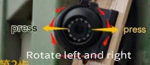
1.2 Enter the WEB BSD calibration menu to check the BSD screen to see if the yellow body line is vertically aligned with the plane of the car body. If not, rotate left and right and press left and right to fine-tune the BSD lens to make it overlap. For WEB BSD menu operation, refer to 2 3 4 article introduction.
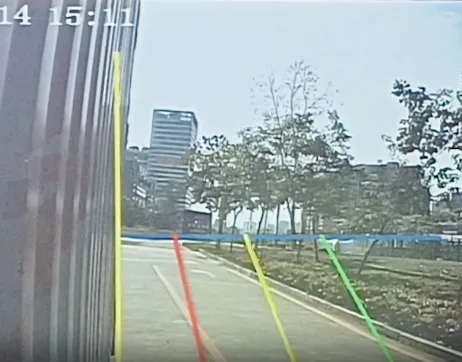
1.3 Check whether the blue alarm boundary line is in the appropriate alarm range above the front or rear of the vehicle. Otherwise, press the BSD lens up and down to fine-tune it to the appropriate position
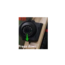
1.4 Fix After adjusting the angle, tighten the screws on the camera base and the left and right sides Front and rear installation angle
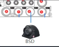
1.5 Insert the camera aviation head into the video input port on the rear panel of the host or the video input extension cable port, usually in the fourth channel port of CH4. You can insert other ports according to the actual application scenario, and change the corresponding channel in the configuration parameters later, and tighten the nut to fix it.

2. Function activation
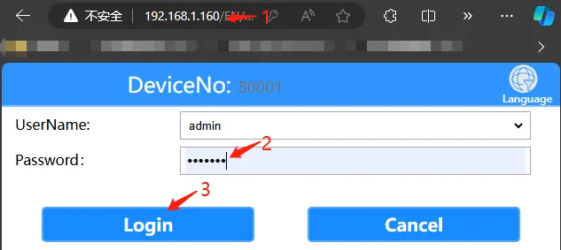
2.1 Open the computer browser and enter the local network IP address of the device, fill in the login password "Adm_123" and click "Login"
2.2 Click "General Settings" >>> "Alarm Settings" >>> "AI Settings" menu
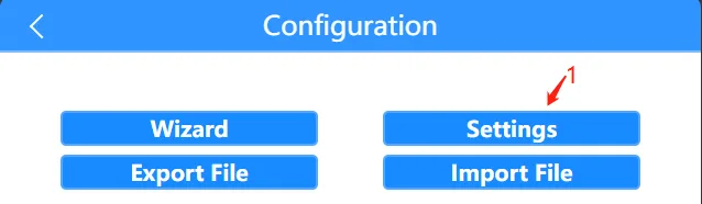
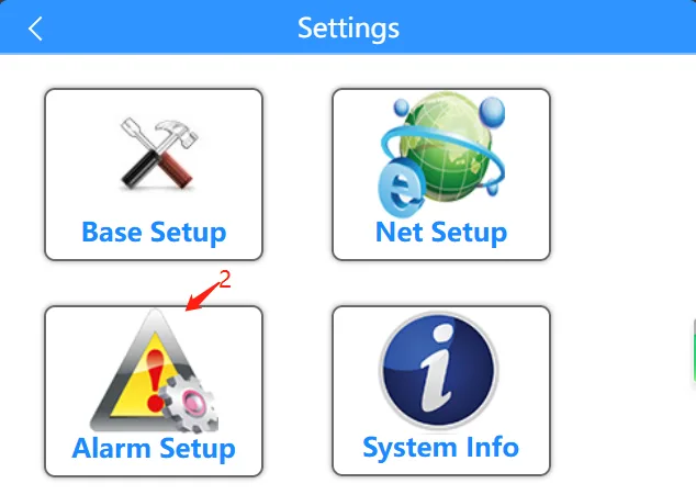

2.3 In the "AI Settings" menu, click to enable R BSD & L BSD function, associated BSD camera inserted into the host rear panel video input channel



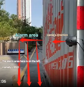
2.4 Distinguishing between left L BSD and right R BSD: The direction is based on the camera lens orientation. The BSD alarm is enabled on the side that is the alarm area. For example, in the following figure, the camera lens orientation is the left side of the alarm area. In this case, the left BSD (L BSD) needs to be enabled.
2.5 Click Enable BSD function in the "AI Settings" menu, insert the associated BSD camera into the video input channel of the host rear panel, and enable the non-fisheye lens function. Whether to enable it here depends on whether the installed BSD lens is a normal or fisheye (deformed) lens. Generally, the non-fisheye lens function is disabled when the front and rear BSDs are enabled and the fisheye camera is used.
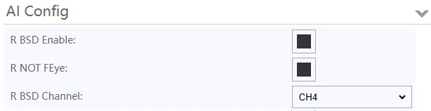
Ps: R BSD = right BSD, L BSD = left BSD, F BSD = front BSD, B BSD = back BSD, which BSD function is enabled according to the actual installation scenario. Note: When multiple AI functions are enabled, please do not conflict with channels including ADAS\DSM\BSD*4. For example, ADAS is associated with CH1 channel, R BSD is associated with CH1 channel. This operation is not allowed, otherwise the algorithm cannot run normally. When R L front and rear BSD are enabled at the same time, check whether the front and rear BSDs have the non-fisheye lens function enabled. If the front and rear BSDs are not enabled, the front BSD will conflict with the R BSD, and the rear BSD will conflict with the L BSD. In this scenario, the four non-fisheye BSD functions cannot be enabled at the same time, otherwise the operation will be abnormal.
2.6 Click "Save" to enable the BSD function and restart the host
3. Camera Configuration
BSD camera channel display screen configuration (such as in WEB BSD calibration menu has been displayed, so you can ignore this step)
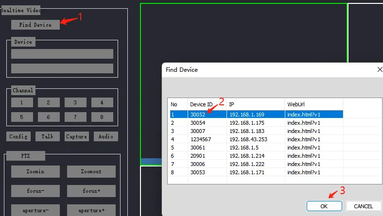
3.1 Configure the BSD camera channel parameters through the "MVMS_NetPlayer" configuration tool, click the link to download to the local computer for installation or consult the technology. Click to download the tool
3.2 Click to search "Find device">>> Double-click the search result and you need to configure the device ID
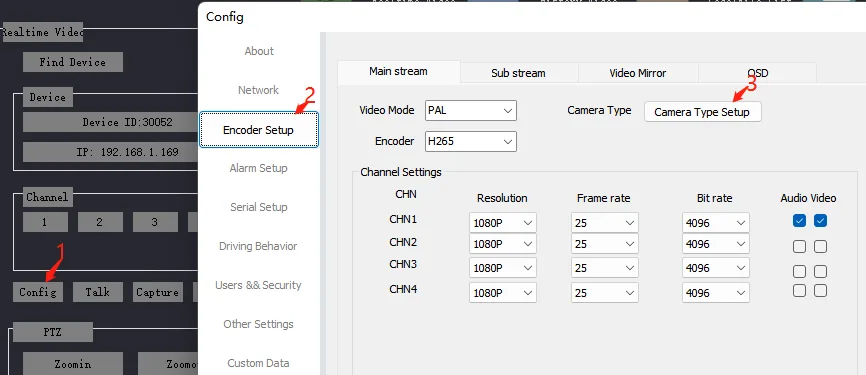
3.3 Click "Configuration" >>> "Encoding Settings" >>> "Channel Type Configuration"
3.4 Select the corresponding resolution camera "1080" in the channel type. Here, we take the BSD camera inserted into the host CH4 third channel as an example, confirm and save.
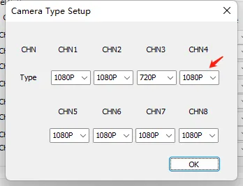
Ps: The current default BSD camera specification is 1080P. If there is any change, please consult the salesperson
3.5 Restart the device to check whether the BSD channel has a picture
4. Calibration configuration
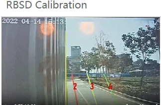
- The steps for enabling left and right BSD are similar. Here we take the right R BSD function as an example. Click the "Right BSD Calibration" column in the WEB menu. Open the calibration menu 4.1 Click to select the blue line (alarm boundary line), click the arrow keys to move it up and down so that it is at the intersection of the sky 4.2 Click to select the white line (horizontal line of the vehicle body), click the arrow keys to move it left and right so that the yellow line is close to the horizontal position of the vehicle body 4.3 Click to select the red line (first-level alarm line), click to select the point "upper point" of the moving line, click the left and right arrow keys to move the upper point to the appropriate position, click again to select the point "lower point" of the moving line, click the left and right arrow keys to move the lower point to the appropriate position Repeat this operation for the yellow line (secondary alarm line) and the green line (third-level alarm line), as shown in the figure below
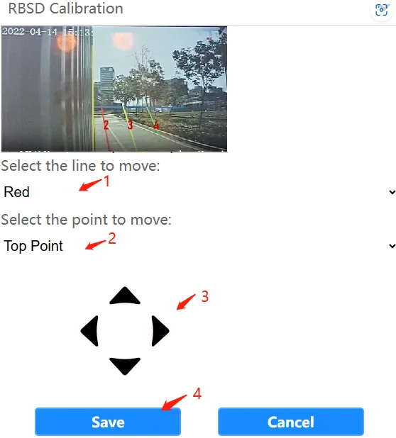
4.4 The operation steps for enabling the front and rear BSD are similar. Here, we take the front F BSD as an example. Click the "Front BSD Calibration" column in the WEB menu to open the calibration menu 4.5 Click to select the left blue line (left boundary line), click to select the point "upper point" of the moving line, click the left and right arrow keys to move the upper point to the appropriate position, click again to select the point "lower point" of the moving line, and click the left and right arrow keys to move the lower point to the appropriate position. 4.6 Click to select the right blue line (left boundary line), click to select the point "upper point" of the moving line, click the left and right arrow keys to move the upper point to the appropriate position, click again to select the point "lower point" of the moving line, click the left and right arrow keys to move the lower point to the appropriate position. 4.7 Click to select the white line (body boundary line), click the arrow keys to move up and down so that the white line is close to the body position 4.8 Click to select the red line (first level alarm line), click the arrow keys to move up and down to the appropriate position, repeat this step for the yellow line (second level alarm line) and the green line (third level alarm line).
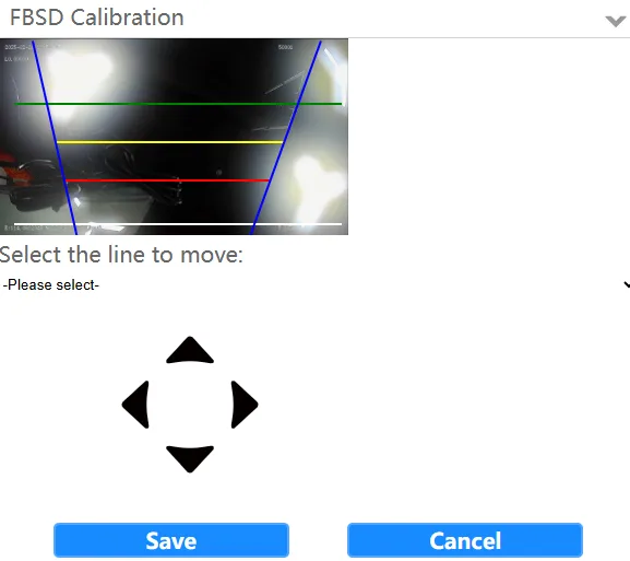
4.9 Click Save to complete the calibration
5. Alarm test
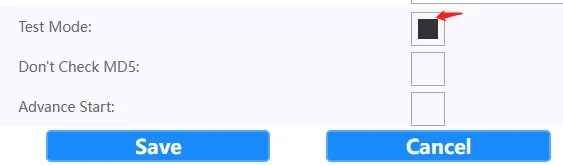
5.1 Alarm occurs in test mode (BSD parameters have been enabled here before, so ignore this step) Click "AI Settings" >>> "Test Mode" in the WEB menu Save and restart the device
5.2 Normal driving mode alarm occurs, GPS antenna needs to be connected and positioning is successful, and the alarm will occur when the previously configured threshold is reached
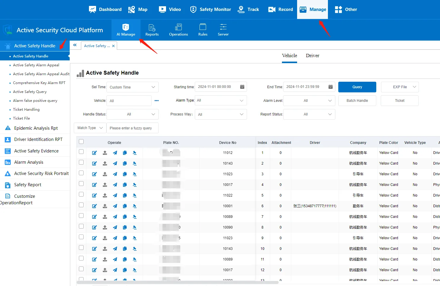
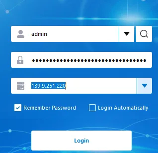
5.3 Log in to the V7 client to view the alarm information
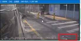
5.3.1 Real-time preview interface OSD alarm message
5.3.2 Active safety panel to view real-time alarm messages
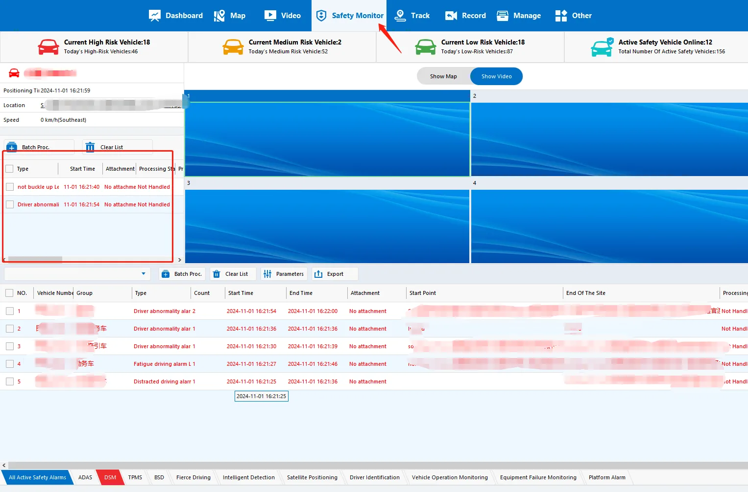
5.3.3 Active safety menu to view historical alarm messages