Installation list
| Name | Quantity | Name | Quantity |
|---|---|---|---|
| MDVR device | 1 | MDVR 485or232 IO harness | 1 |
| Remote controller | 1 | Display | 1 |
| Oil level sensor and calibrator | 1 | Common wiring tools | n |
Necessary instructions
- Here we take MX-FLS-01-01 (232zy) and MX-FLS-01-02 (485zy) capacitive oil sensors as examples. For other models, refer to the following 232 and 485 wiring according to the protocol type. For details on the device menu configuration, see the "Model Corresponding Configuration Parameter Table" below. Some oil sensors may have different baud rates. Please refer to the manufacturer's oil sensor documents or ask our technical staff for details. Model corresponding configuration parameter table
| Model | Serial port index | Serial port function | Protocol type | Baud rate |
|---|---|---|---|---|
| MX-FLS-01-01 | RS232 | Oil level sensor-1 | Type1 | 9600 |
| MX-FLS-01-02 | RS485 | Oil level sensor-1 | Type1 | 9600 |
| DS1309-B | RS232 | Oil level sensor-1 | Type1 | 2400 |
| MX-FLS-02-02 | RS485 | Oil level sensor-1 | Type2 | 19200 |
| MX-FLS-02-01-NH | RS232 | Oil level sensor-1 | Type2 | 9600 |
| MX-FLS-02-01 | RS232 | Oil level sensor-1 | Type1 | 9600 |
Actual image:
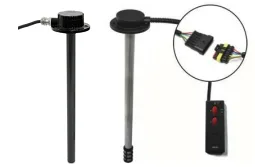
MX-FLS-01-01, MX-FLS-01-02
Operation steps
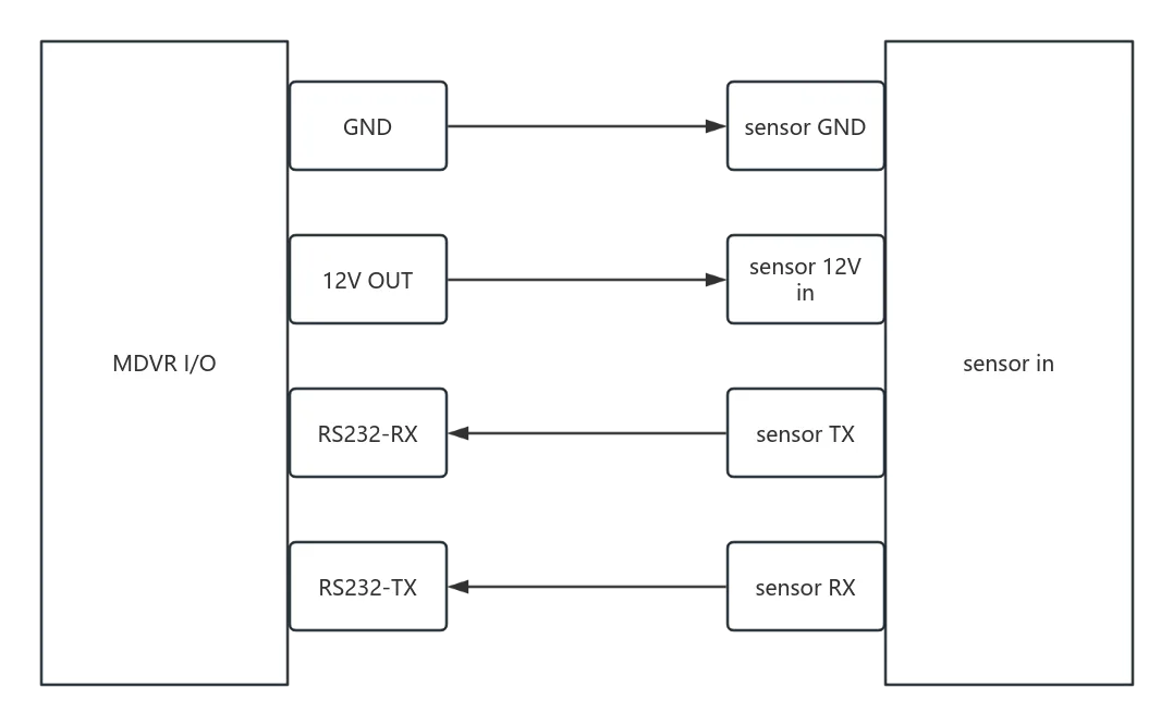
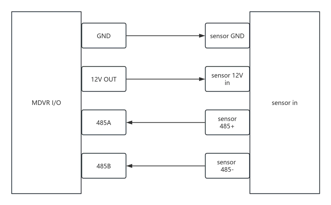
1. Wiring
**MX-FLS-01-01 (232) **
**MX-FLS-01-02 (485) **
2. Device menu configuration
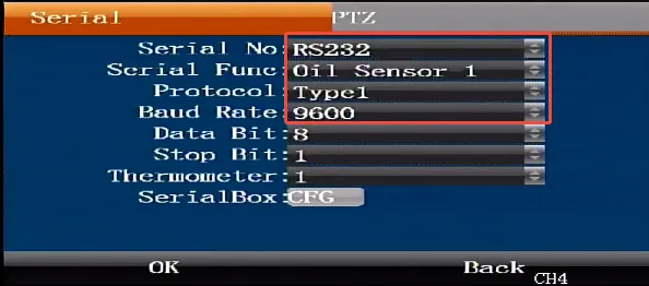
MX-FLS-01-01 (232)
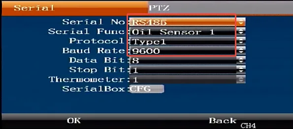
Remote control enters menu>>Settings>>Serial port settings>>Serial port, serial port index configuration RS232, serial port function oil level sensor-1, protocol type type1, baud rate 9600, other parameters are default, confirm save and restart the device to take effect.
MX-FLS-01-02 (485)
Remote control enters menu>>Settings>>Serial port settings>>Serial port, serial port index configuration RS485, serial port function oil level sensor-1, protocol type type1, baud rate 9600, other parameters are default, confirm save and restart the device to take effect.
3. Oil rod cutting
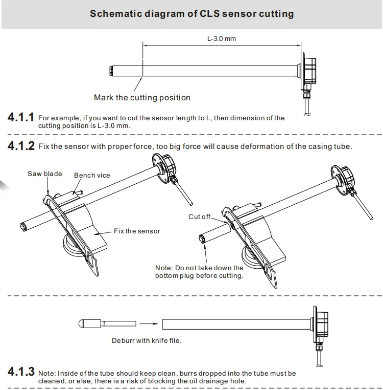
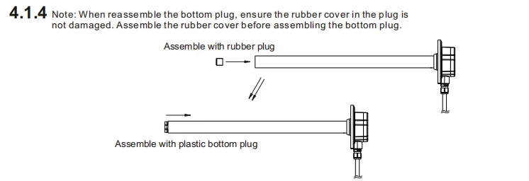
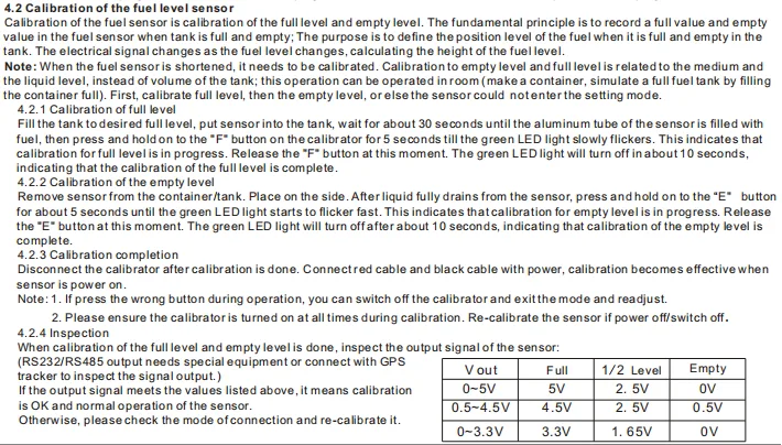
- Sensor length adjustment and calibration: 4.1 . Length adjustment (see the figure below) Users can shorten the sensor according to actual needs. The steps are as follows: 4.1.1 Users can determine the length of the sensor according to their needs; 4.1.2 Use a saw blade to cut off the unnecessary parts; 4.1.3 Use a file to remove burrs on the pipe mouth and shaft; 4.1.4 Remove the bottom plug and reinstall it in the sensor
4. Oil sense calibration

5. Oil Sensitivity Test
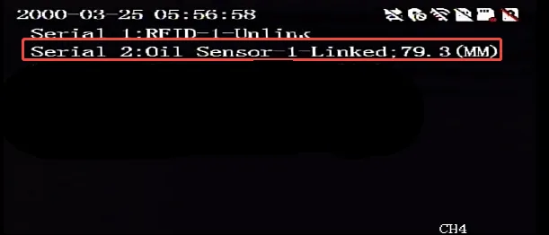
- Local View After completing the installation, calibration and wiring, power on the device, press the remote control direction key to go to the serial port status to check whether it is connected and display the current oil value
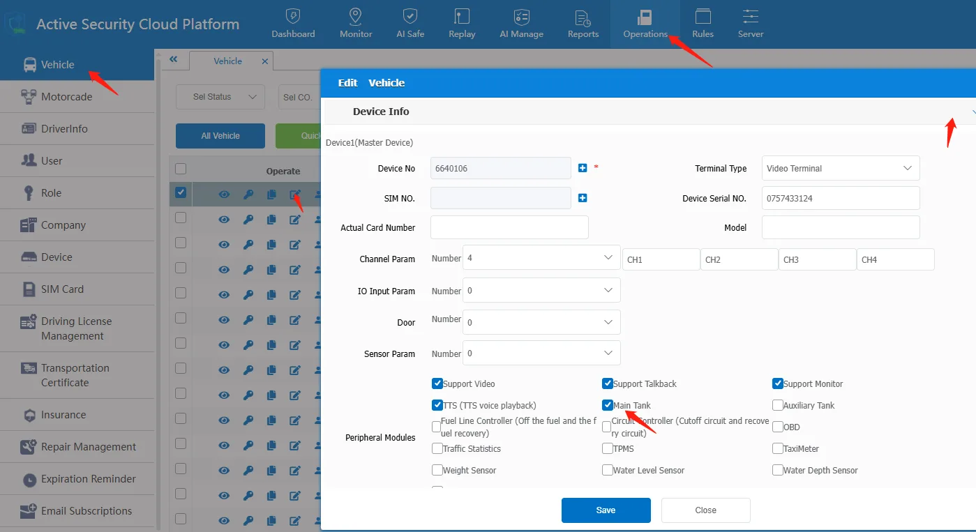
- Remote Platform View 2.1 Log in to the platform to enable the vehicle oil sensing function, in Information Management--Operation Management--Vehicle Information--Edit--Check "Oil Sensor"--Save and Enable.
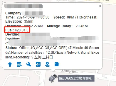
2.2 After configuration is completed, you can view the data in the map bubble box
6. Remote calibration
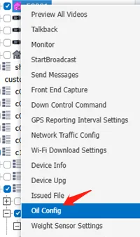
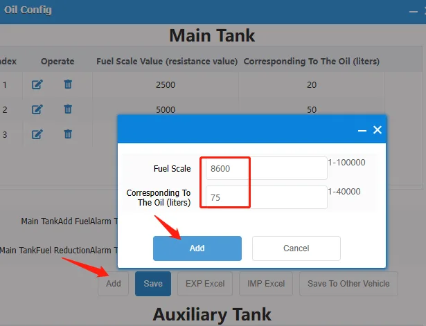
When the displayed oil volume is still biased, you can log in to the platform to configure several sets of proportional data calibration. Log in to the platform and select the vehicle--Oil volume sensor settings--Add Fill in the currently reported value and the actual measured value of the vehicle, and configure the ratio several times to improve accuracy.
7. Frequently Asked Questions
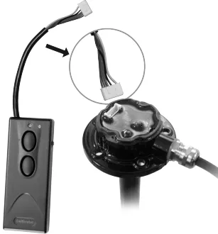
First, how to calibrate the sensor? A: Put CLs into the oil tank (or calibration container), fuel to full position, after the oil fully enters the sensor, connect the calibrator, turn on the calibrator switch, hold down the "F" key, release the button after the green light flashes, and let the green light blink to stop; Take the sensor out of the oil tank (or calibration container) and let the oil flow back to the oil tank (or calibration container). After the oil drops, hold down the "E" key and release the button after the green light flashes, and let the green light blink until the calibration is completed; The calibrator should be connected at all times during calibration and should not be powered off. The calibration sequence must first be full and then empty, otherwise the calibration will not succeed.
why is the calibrator not working? A: First check whether the battery has power, a new battery can calibrate 15 to 20 CLs; Then check whether the indicator light on the calibrator is normal.
When the calibration is full, the green light will flash according to the instructions, but the green light will not flash when the calibration is empty. A: First confirm whether the battery power is sufficient, after connecting the calibrator, the red light is slightly on or not on, indicating that the power is insufficient; Then confirm whether the calibrator is related to the failure to reopen or the calibrator is disconnected from the sensor.
Why is the cLs output not full (or inaccurate) after the sensor is calibrated and fully fueled? Answer: Refueling has not reached the designated full position. If the calibration position is in the small hole below the sensor head, the actual amount of fuel does not reach the small hole; Under normal circumstances, when refueling, as long as it is added to about 90% of the tank, it has reached the full tank that we often say, so if the full position is calibrated below the sensor head, the value obtained is about 4.5V (about 90% of the oil).
How do I ensure that the CLs is calibrated in a full tank position? A: Directly calibrate and set the full and empty positions on the fuel tank; If on-site calibration is not possible, a rod can be used to measure the height of the liquid level in the tank when the tank is full, and mark it on the rod. Then the CLS can be marked at the same height and refueled in the self-made measuring cylinder to the marked position to mark the full position.
Why does the display screen show "not connected" after wiring? Answer: Cross-replace the two 232 or 485 serial port cables and reconnect them. It may be that the labels are wrong.
Why does the display screen show "connected" but no data? Answer: It cannot be used for conductive media such as water, so diesel, gasoline, and kerosene need to be added for testing and use.