Installation List
| Name | Quantity | Name | Quantity |
|---|---|---|---|
| MDVR AI Device | 1 | MDVR 232 IO Harness | 1 |
| Remote Control | 1 | Display Screen | 1 |
| AI Alert | 1 | Common Wiring Tools | n |
Important Notes
- The AI alert is used to trigger AI alarms in conjunction with the MDVR AI device. Therefore, the device itself must support AI functionality and be configured with relevant parameters to trigger the alarm.
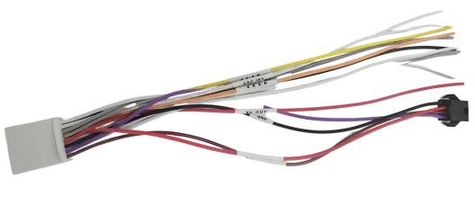
- MDVR 232 wiring harnesses are typically shipped with 4-pin connectors for direct insertion.
- Related document links: Firmware Download/ Upgrade Guide/ AI Configuration
Model-to-Model Configuration Parameter Table
| Model | Serial Port Index | Serial Port Function | Protocol Type | Baud Rate |
|---|---|---|---|---|
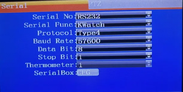
| MX-AITXQ-02-V1.0 | RS232 | KWatch | Type4 | 57600 |
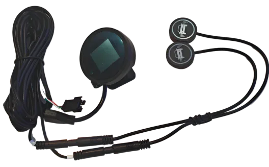
Actual Product Images: AI Reminder Actual Product Image
MDVR IO Tail Cable Actual Product Image
Operation Steps
I. Device menu configuration
Remotely access the menu >> Settings >> Serial Port Settings >> Serial Port. Configure the serial port index as RS232, serial port function as KWatch, protocol type as Type4, and baud rate as 57600. Confirm, save, and restart the device for the changes to take effect.
II. Alarm Test After restarting, triggering any AI alarm will activate the AI alert. Refer to the instructions for enabling the alarm function.
For example, triggering MDVR AI forward collision, lane departure, or BSD alarms will display corresponding icons on the AI alert.
III. Installation Notes
Distinguishing Between Left and Right Humanoids
 The left humanoid has a fragile label, the right humanoid does not.
IR and Photosensitive Sensor Positions
The left humanoid has a fragile label, the right humanoid does not.
IR and Photosensitive Sensor Positions
The IR receiver is located on the top front of the device and is used to receive remote control signals; the photosensor is located on the bottom front of the device and is used for ambient light detection.
Display Protection
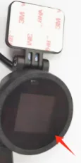 The AI reminder display screen has a protective film. Please do not remove it before use to prevent scratching the screen.
IV. Self-Test Mode Test
How to Enter Self-Test Mode
Point the remote control at the device's IR receiver.
Press the MUTE button on the remote control to enter self-test mode.
The system will display alarm images and left and right humanoid indicators in sequence.
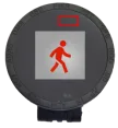
Self-Test Verification Standard
| Inspection Item | Normal Status |
|---|---|
| Alarm Image Display | Displayed normally in sequence |
| Left Humanoid Indicator | Lights up first (side with fragile label) |
| Right Humanoid Indicator | Lights up last (side without label) |
Exit Self-Test
Press the MUTE button on the remote control again. Exit self-test mode and return to normal working status.
V. Troubleshooting Common Problems
| Phenomenon | Possible Causes | Solutions |
|---|---|---|
| Left and right human figures do not light up during self-test | Loose connection cable | Check if the wiring harness is securely plugged in |
| No display | Protective film obstructing or hardware failure | Check the protective film and confirm normal power supply |
| AI recognition is not sensitive | Face database not imported or threshold setting is incorrect | Re-import face photos and adjust sensitivity |
| Serial communication fails | Baud rate mismatch | Confirm that the host and the reminder's baud rates are consistent |