Prerequisites:
- The device and computer are in the same LAN segment, and the computer can ping the local IP address of the device
- Or the device with WiFi module is switched to AP mode, and the computer connects to the AP hotspot to access the 192.168.42.100 address
- The device is already in the shipping state (AI has been authorized, the algorithm has been imported)
Flowchart

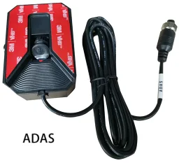
Physical picture
Operation steps:
1. Camera installation
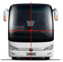
1.1 With the center axis of the vehicle as the center, the intersection of the horizontal line above the wiper and the central axis is the best installation position for the device (be careful not to be blocked by the wiper). The center axis position can be determined with a tape measure, and the horizontal line position can be determined with a level, as shown in the following figure:
1.2 After wiping the inner surface of the windshield clean, tear off the camera 3M adhesive protective film and lens protective film and then paste and install it inside. When pasting, make sure that the camera is in a horizontal installation position (you can use a level). After pasting, press for about 30 seconds to ensure that there are no bubbles in the 3M adhesive.
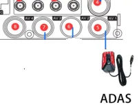
1.3 Insert the camera aviation head into the video input port on the back panel of the host or the video input extension cable port, usually in the first channel port of CH1. You can insert other ports according to the actual application scenario, and change the corresponding channel in the configuration parameters later, and tighten the nut to fix it.

2. Function activation
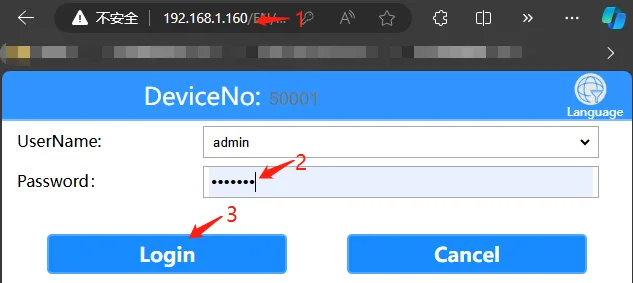
2.1 Open the computer browser and enter the local network IP address of the device, fill in the login password "Adm_123" and click "Login"
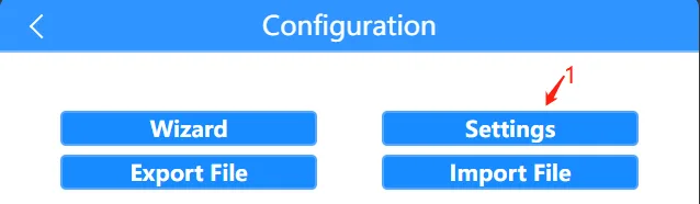
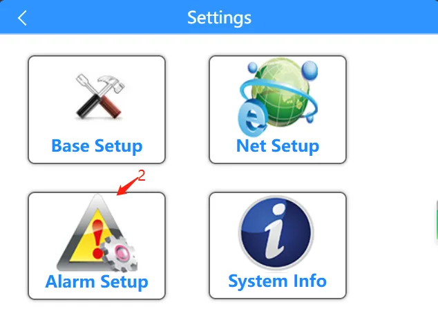
2.2 Click "General Settings" >>> "Alarm Settings" >>> "AI Settings" menu
2.3 In the "AI Settings" menu, click to enable the ADAS function, and associate the ADAS camera to insert into the host rear panel video input channel

2.4 Click "Save" to enable the ADAS function and restart the host
3. Camera screen configuration
ADAS camera channel display screen configuration (such as in WEB ADAS If the vanishing point menu has already been displayed, you can ignore this step)
3.1 Configure the ADAS camera channel parameters through the "MVMS_NetPlayer" configuration tool, click the link to download to the local computer for installation or consult the technology. Click to download the tool
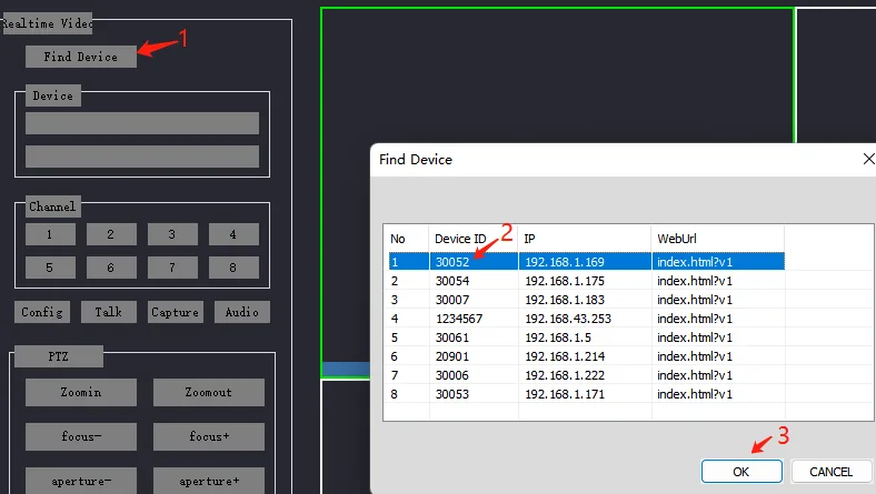
3.2 Click to search "Find device">>> Double-click the search result and you need to configure the device ID
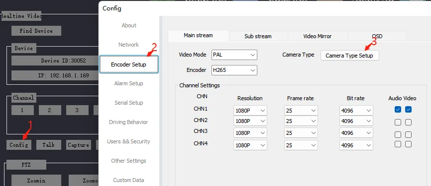
3.3 Click "Configuration" >>> "Encoding Settings" >>> "Channel Type Configuration"
3.4 Select the corresponding resolution camera "1080P" in the channel type. Here, we take the first channel of host CH1 when installing the ADAS camera as an example, and confirm and save.
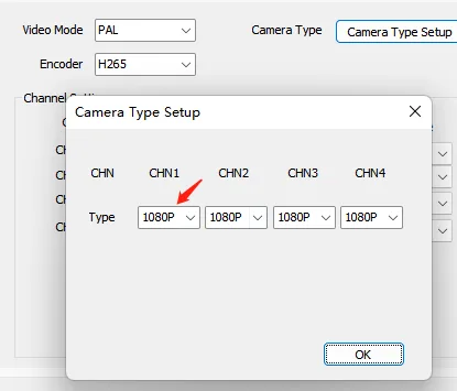
Ps: The current default ADAS camera specification is 1080P. If there is any change, please consult the salesperson
3.5 Restart the device to check whether the ADAS channel has a picture
4. Vanishing point and calibration configuration
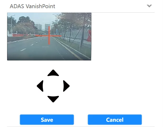
4.1 Click the "ADAS Vanishing Point" column in the WEB menu Open the vanishing point menu, click the arrow keys to move the red cross to the skyline in front of the ADAS lens, and click Save to complete the vanishing point calibration
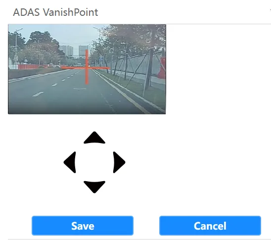
Ps: When the horizontal line of the red cross cannot be completely overlapped with the skyline (the junction of the sky and the earth) after moving it in the menu, you can loosen the fixing screws with the matching ADAS camera "7" shaped hexagonal tool, then gently buckle the pointer and slide it to the required scale, and then tighten the fixing screws. Use the "up, down, left, and right" keys to make fine adjustments so that the horizontal line of the red cross coincides with the skyline in the distance of the screen. To refresh the ADAS screen, you can refresh it by refreshing the WEB interface through the browser
4.2 Click the "ADAS Calibration" column to open the calibration menu, fill in the measured vehicle width, installation height, distance to the left side, distance to the front of the vehicle, and distance to the front wheel information and save it. The lens focal length and sensor size should not be changed by default.
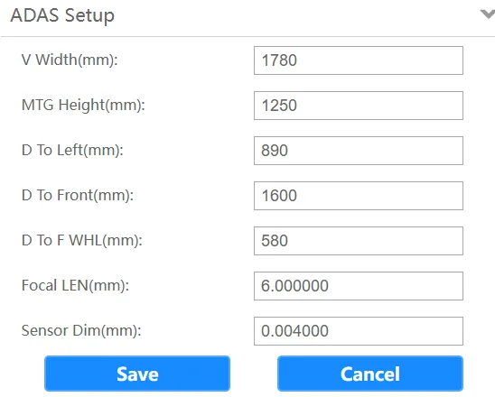
4.2.1 Vehicle width: Use a tape measure to measure the width of the vehicle on both sides. The width here refers to the widest part of the vehicle body, which is usually the widest distance between the two wheels
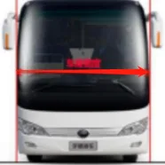
4.2.2 Installation height: Use a tape measure to measure the distance from the vehicle ground to the center point of the ADAS camera lens
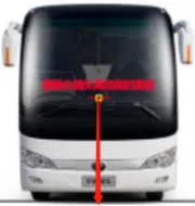
4.2.3 Distance to the left side: Use a tape measure to measure the distance from the left side of the vehicle to the center point of the lens of the ADAS camera
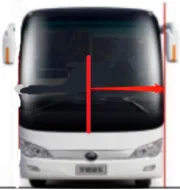
4.2.4 Distance to the front of the vehicle: Use a tape measure to measure the distance from the front of the vehicle to the center point of the lens of the ADAS camera. Generally, the front of a car protrudes and the distance needs to be measured. If the front of a bus or a public bus is flat, it does not need to be measured. Just fill in 0 here.
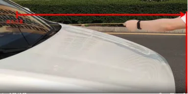
4.2.5 Distance to the front wheel: Use a tape measure to measure the distance from the center of the front wheel to the center of the lens of the ADAS camera
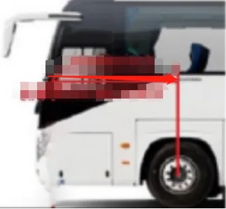
When the wheel is in front of the camera, fill in the measured value with a positive number +
For example: 580mm
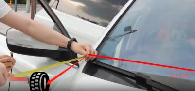
When the vehicle is behind the camera, fill in the measured value with a negative number -
For example: -680mm
4.3 After filling in the above parameters, click Save
5. Threshold and sensitivity adjustment
5.1 Click ADAS Sensitivity Adjustment in the WEB menu and fill in HMW (distance detection), FCW (front vehicle collision), LDW (lane deviation), PCW (pedestrian collision) speed threshold parameters Note: The alarm will only occur when the vehicle speed reaches the value of the corresponding alarm type
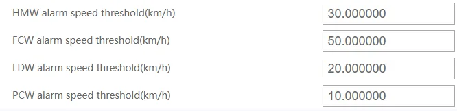
5.2 Fill in HMW (distance detection), PCW (pedestrian collision), FCW (front vehicle collision) Duration threshold Description: The alarm will be triggered only when the duration of the corresponding alarm type reaches the configured value, except that the PCW alarm threshold will be triggered only when it is less than this value

5.3 Fill in the lane offset distance threshold Description: This parameter applies to both left and right lanes. When 0 is configured, the alarm will be triggered only when the wheel hits the line. When a negative number is configured, such as -5, the alarm will be triggered only when the wheel hits the line 5cm past the line. When a positive number is configured, such as 5, the alarm will be triggered only when the wheel is 5cm away from the line.

5.4 Fill in the pedestrian crossing interval configuration Note: The next alarm will only occur when the time interval between the pedestrian crossing alarm and the next alarm reaches the configured value

After filling in, click Save and restart the device to take effect
6. Alarm test
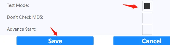
6.1 Alarm occurs in test mode Click "AI Settings" >>> "Test Mode" in the WEB menu Save and restart the device
6.2 Normal driving mode alarm occurs, the GPS antenna needs to be connected and the alarm will occur when the previously configured threshold is reached if the positioning is successful
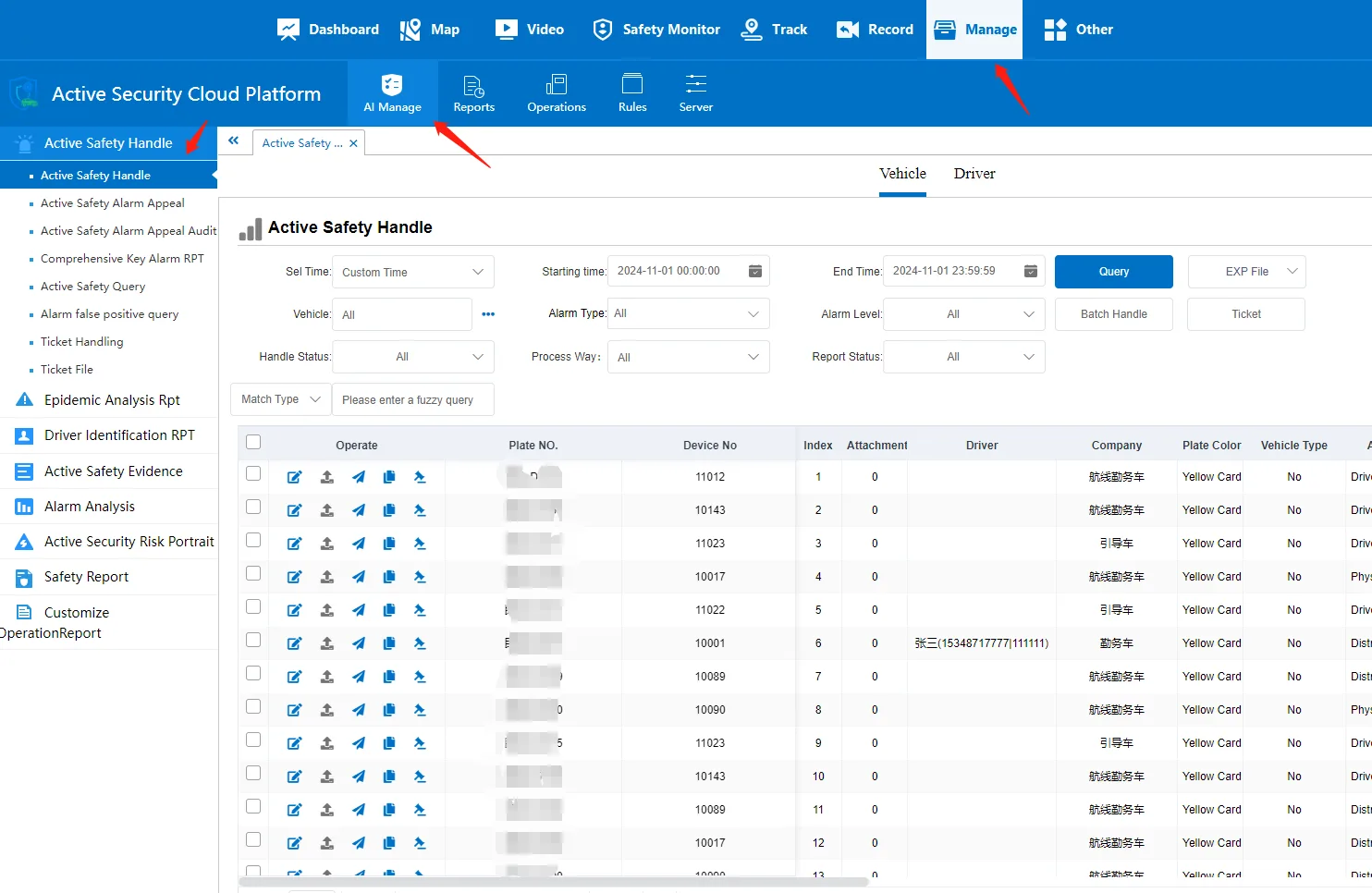
6.3 Log in to the V7 client to view the alarm information
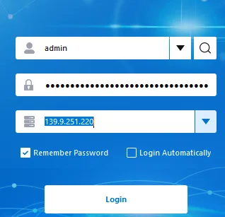
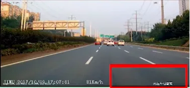
6.3.1 Real-time preview interface OSD alarm message
6.3.2 Active safety panel to view real-time alarm messages
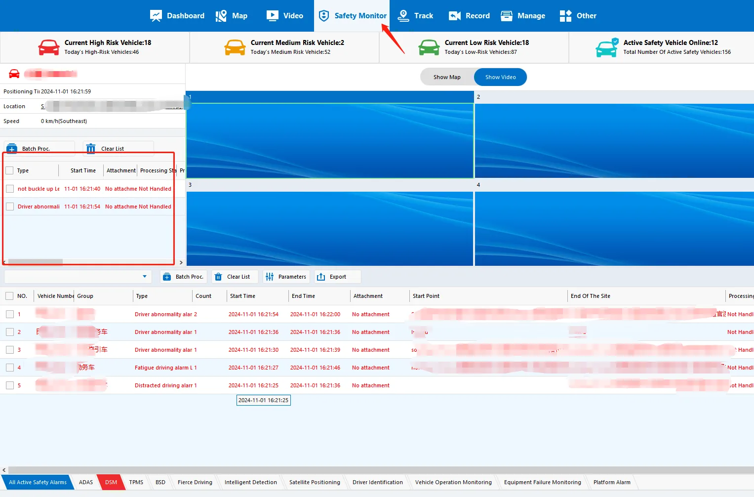
6.3.3 Active safety menu to view historical alarm messages